Fiber optic networks have evolved from a series of simple point to point links, which served mainly as transport network and feeder to further ADSL or other copper last mile networks to more complex and more evolved concepts.
In these series of blog, we will review these steps one by one and will follow this growth in speed, complexity and functionality and this will give us good background to understand modern fiber networks and how they are planned, built and maintained now.
Fiber networks, or at this stage – stage 1, all consisted of P2P – or point to point links, with a basic concept depicted on this scheme below:
 Figure 1: Step 1: Dawn of Fiber Links, P2P scheme
In such schemes, there was 1 single wavelength used and one optical bit per electrical signal (0 or 1). Only after introduction of 100Mbit/s optical link speeds, FDDI and Fast Ethernet, 4 electric bits were used to be encoded in 5 optic bits.
Components that was used in such P2P schemes were basically same optoelectronics, fiber cables, connectors and splices.
Naturally, transmission distances were limited because of signal distortion, which was caused or by power loss, or pulse spreading from dispersion.
So, in order to extend transmission distance, engineers started to use regenerators, which first converted signal back from optical electrical, and then vice-versa.
It looked somewhat this way:

Figure 2: Optical Signal Regeneration in early phases
Now, this was definitely not cheap way to operate at all, however, good thing was that it was pretty easy to test and maintain such systems – just connect optical measurement test equipment at the end of links and measure the power loss.
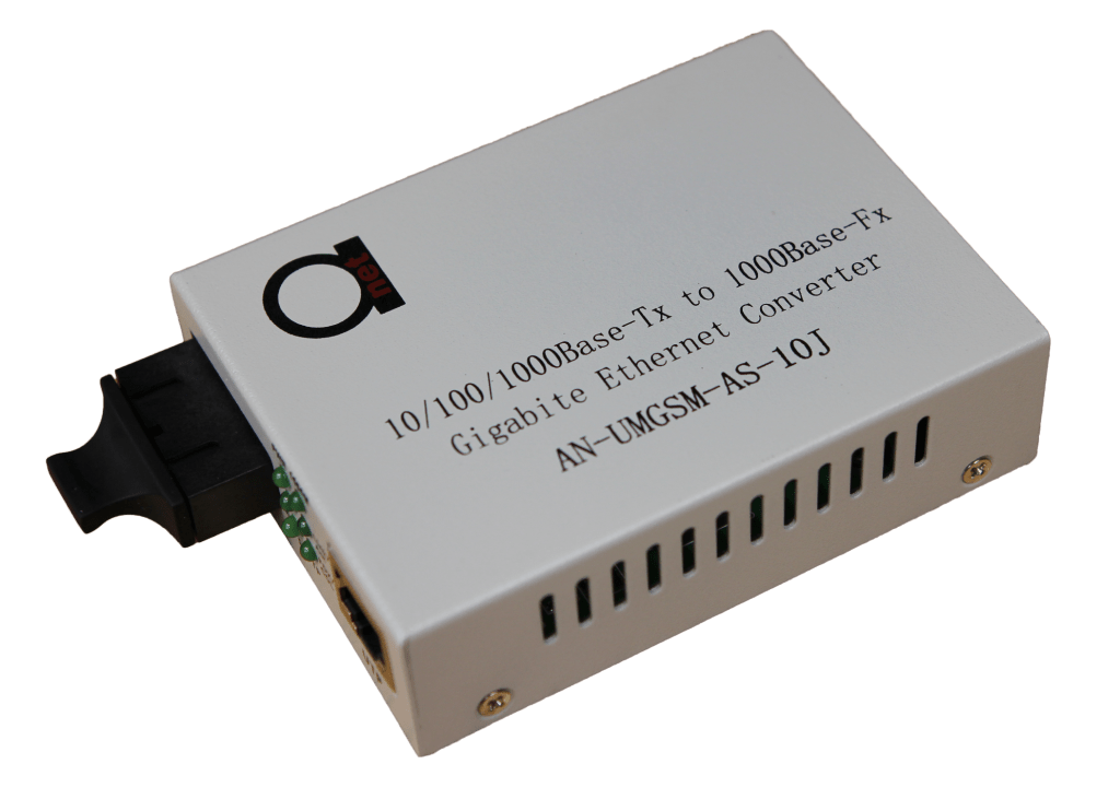
Some close (but not exact) example of such link is good, old & reliable and still widely used Fiber Optical Media Converters.
Figure 3: Gigabit Ethernet Media Converter used in P2P type optical links


