Now, at this stage fiber already got pretty good penetration in many countries, and it quickly became obvious that once installed – (laid in ground, hanged between buildings, as an extreme example – under the see), it has just definite amount of fibers and once you had used them – that’s it. So, you needed now think, how you can more effectively use and re-use your fibers.
This is where WDM (Wavelength Division Multiplexing) technology kicked in. What it allowed to do, is to send different wavelengths over the same fiber – and initially it was 850nm/1300nm on multimode fibers and 1310nm/1550nm on single mode fibers.
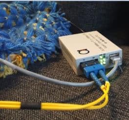
This is the classic example of WDM media converters, like this one:

Thus, these wavelengths first needs to be combined before sending in the fiber, and then later separated again at the ends of fiber links.
To do that, in fiber equipment design special passive devices, called WDM multiplexers and WDM de-multiplexers where added in principal scheme. Another good example of this principle can be illustrated using concept of CCTV Video Over Fiber converters, which use 2 wavelengths for carrying video signal from cameras to DVR, while using another wavelength to carry PTZ type serial data for controlling cameras (tilt, zoom) etc. Real life example of these are one of our projects in Thailand.
One more good example – E1 signal. It’s clear, that E1, as TDM signal must be duplex, and synchronous, nevertheless, using this E1 WDM fiber modem, you can achieve that using 1310/1550nm separation.
Now, the scheme you saw in Step 1 and Step 2 transformed to have such outlook:

Figure 1: WDM principle – adding WDM muxes and WDM de-muxes allows to use fiber for sending 2 different wavelengths same time
Now, using this WDM technology allows us to carry a unique data stream to both sides, thus increasing a capacity of fiber.


