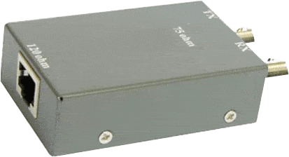
An impedance converter is generally a device that is used to convert the very high impedance pH electrode signal to a low signal. The range of the impedance signal varies from less than 1 KΩ to around 1000 MΩ. 75 120 baluns below are the good example of this. The uses of an impedance converter can be beneficial in conjunction with the metal electrode as well. This type of converter is directly screwed onto the head of the electrode and it largely eliminates the interferences caused due to the problems of moisture, electrical fields from the power cables and dirt. Basically a coaxial cable is enough as being the connecting cable between the transmitter and the impedance converter. Even the long distances that are found between the transmitter and the sensor can be easily covered. Thanks courtesy to the in-built lithium battery that the impedance converters do not require to depend on any outside power supply.
The negative impedance converter or what is popularly known as the NIC is actually an operational amplifier configuration that contributes in acting like a negative load. By using such a converter, it is really useful to let the real general actually work like a perfect generator. The impedance converter device comprises of the following items:
- A conductive conductor (external) with connection locations for the electrical lines
- Electrically conductive conductor (internal) with connection locations
- Dielectric that is arranged between the internal and external conductor
The external conductor that is used in the impedance converter consists of a base surface that is bounded by side walls, helping in the formation of an external conductor with an opening that is opposite to the base area and an internal space. In this internal space, the internal conductor is carefully arranged. Both the external conductor and the internal conductor are properly insulated from each other by the use of the dielectric.
The impedance converters are used in the telephone switching network and applications. In various such switching applications like the central telephone office network, the path of transmission is provided between the given output and input lines by the establishment of the cross point connections in the telephone switching networks. In such a type of switching network, it includes the plurality of the switching matrices between the groups of output and input lines with each of the stage containing one or more than one switching matrices. There are some of the switching networks in which the matrices are interlinked in order to provide a paths plurality between the each line of the group’s input line and output line.
By using two or more than two current conveyors, one can conveniently realize the floating impedance converters. A current conveyor is generally a flexible analog device which is used with the various circuit components in order to implement the different functions of the analog signal processing. The circuits that are based on the op-amp are comparatively convenient to design as the voltage op-amp’s behavior can be easily approximated with the use of a few easy design rules. Last but not least, for connecting the impedance converter device to the electrical lines, there are connection locations present in both the internal as well as the external conductors so that the user can conveniently avail the benefits of the impedance converter.
For example these baluns 75 120 ohm are used for G.703/G.704 impedance matching purposes.
Here is how it looks like:

You can see, that RJ-45 connector has impedance of 120 hm, and BNC coax type connectors are 75 ohm.
Related products: Impedance converters (baluns)


