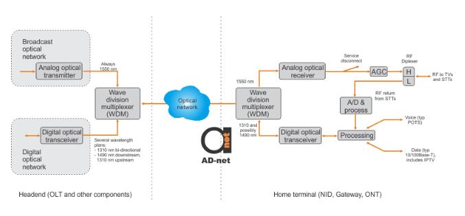
This article will be showing the reference HFC-compatible FTTH architecture. As it could be seen from Figure 1, the tapped bus architecture been used for carrying broadcast video and data through generic FTTH network. The video headend is being terminated in an analog optical transmitter of high quality, while its headend is identical to the one for HFC. In order the optical signal being amplified, broadcast TV is always using the 1550 nm signal. In order to amplify the signal, sometimes Erbium-doped fiber amplifiers (EDFAs) being used.

Figure 1. Elements of an FTTH network.
The data layer has different from broadcast frequency spectrum and is completely separated from it. There are two plans for data, while they are sharing the same fiber as the broadcast video. First plan is using 1310 nm digital signal in the optical network while sending signal in both directions.
Second plan is using different wavelengths for upstream and downstream. While upstream wave of 1310 nm does not give any troubles, downstream wave of 1490 nm is interfering with broadcast video of 1550 nm due the stimulated Raman scattering (SRS). The problem might be controlled only by implementing optical signal level control, managing number of splits in the system and distances covered. Nevertheless using the bi-directional transmission for data avoids that problem, and has been used for carrying analog video signal for several years already.
Standard Gigabit Ethernet connections being used for connecting headend data structure to the digital optical transceiver. This transceiver together with some data processing maintain the OLT. Inserting the Gigabit Ethernet blades will allow using other data elements. This makes HFC interfaces and FTTH interfaces are quite inter-compatible.


