Goal of this article is to define latency requirements of the data center. It will be defined through discussion of cut-through and store-and-forward switching paradigms. Main points discussed in this article are:
- Latency requirements are main criteria for selecting LAN-switches and other related equipment.
- Most networking environments support both switching topologies.
- Switch choice is based on function, performance, cost, and port density. These points are considered after latency requirements are met.
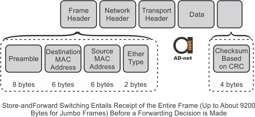
Whether cut-through or store-and-forward Layer 2 switches are used, forwarding decision is based on destination MAC address inside data packets. Decision is made when data packet is fully received, and frame integrity is checked. Theoretically cut-through switch receives only first 6 bytes of a frame containing DMAC address. However, for technical reasons, switch evaluates couple more bytes before proceeding.
Following steps are taken during store-and-forward Ethernet switching:
First, switch receives Ethernet frame. At the end of the frame, is a checksum field. It is compared against switches own FCS (frame-check-sequence) calculation. That way packet is evaluated for physical and data-link errors. if the integrity is ok, packet will be forwarded.
Cut-through switch will forward any frame it receives because it does not evaluate FCS.
Store-and-forward switches support automatic buffering. This means that forwarding to any Ethernet speed interface can be done automatically due to fact that switches architecture allows storing entire packet. Additional ACL (Access Control List) evaluation is not necessary for the same reasons.
Cut-through switching does not drop invalid packets, but rather flag them and forward them further the network. While preparing for forwarding, cut-through switch can fetch additional bytes defined in EtherType field. it could be anything from IP and transport-layer headers to any other configuration.
Main advantage of cut-through Ethernet switching is in its ability to begin packet forwarding within milliseconds of receiving it, regardless of its size. It is noticeable when transmitting large size frames or in HPC (High-Performance Computing) applications.

In most enterprise environments, latency difference between cut-through and store-and-forward solution is neglectable, since it is measured in tens of milliseconds. For the windowed protocols like TCP, response time is decreased for cut-through switching, essentially making latency the same for both methods.
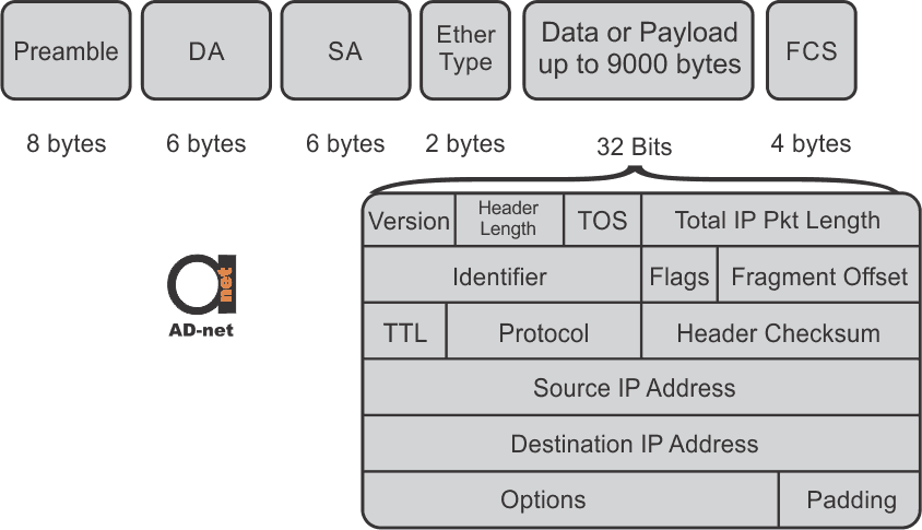
Advanced Layer 2 switches require more information than just MAC addresses of source and destination to select physical interface. In order to offer better flexibility and packet distribution, cut-through switches must be able to incorporate IP addresses and transport -layer port numbers. Well-designed cut-through Ethernet switch supports ACL, which determines whether packet needs to be forwarded or denied.
Under-run condition is the scenario when receiving data rate is less than or faster than transmitting data rate. Example is 1 Gbps ingress and 10 Gbps egress situation. Egress port transmits 1 bit of data in only 0.1 the time of the ingress receives. To avoid having “gaps” on egress side, whole frame needs to be received before proceeding with transmission.
Sometimes, it is possible that egress port could be congested, due to port being busy. In this case switch buffers the packet that has already received transmission decision. Network designer should ensure that access-layer traffic from client would not exceed egress capacity going to the server. Typically, lower speed user connections join in the aggregation switch, which is connected to the core of the network.

The reason for cut-through Ethernet technology making it back to modern centers is hidden in modern applications, which could benefit from lower latencies and consistent packet delivery. Furthermore, modern switches can determine whether packet is applicable for transmission or not, by accessing information deeper inside packet.
Modern data centers can provide access to virtual machine, which could be used for research, manufacturing, data-mining, and engineering. These virtual machines are located on commodity of servers. To make system work flawlessly, multiple software and algorithm solutions were developed, which allow execution of different parts of code by different servers. That way, processing time decreases dramatically. Data is being distributed across many individual processors for execution, and results are gathered back together.
In most scenarios, minimum requirement for app-to-app latency is 10 microseconds, while cut-through solution can offer latency of 3 microseconds, if the network is properly designed. Applications that are very latency dependent are tightly coupled applications, and require ultra-low-latency characteristics.
First step in designing suitable network for HPC environments is in determination of required data center latency. After switching platform has been chosen, one must ensure that chosen switches satisfy all functional and operational requirements without affecting performance and latency.
Monitoring, troubleshooting, and capability to debug packets within switch, should be supported by enterprise vendor. Warning email could be set-up to notify administrator in case of system failure. Switch could either be configured and perform as desired, or could be oversubscribed and have lower performance, as long as limitations are understood and accepted.
Total cost of switch also includes expenses for staff training, and possible monitoring tools. Latter ones could dramatically lower the troubleshooting and fixing time in event of problem occurrence.
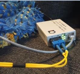
Why these things are important to understand in connection to even such simple devices as Fiber Media Converters?
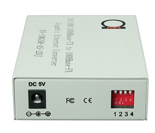
If you take some of our new version media converters, you’ll notice that back panel has some dip switches:

Now, that’s where these terms come in play.
Enabling cut through mode via dip switch here, you’ll be able to have jumbo frames passing through, just like explain above in theory.
Another dip switch here is responsible for LLF feature, explained here.


