In our previous article, Everything you need to know about POTS (Plain Ordinary Telephone Service) and Analogue Phone Systems – Master 101 class we looked at the basics of POTS telephone systems, such as Tip & Ring, Twisted Pair, Balanced Signalling, and Call Progress Tones.
In this article, we are delving deeper into POTS, and we’ll cover such topics as Dialing Plan, Address Signaling, Pulse Dialing, Touch Tone or DTMF, In-Band Signaling, Hidden Buttons and Caller ID
Let’s get a ball rollin’!
Network Addresses: Telephone Numbers
When a request to communicate has been acknowledged with a dial tone, the network needs to be told where the call is to be connected to. Generally, the network address is the piece of information that identifies the final destination of the connection in a network. For POTS, the network address is called a telephone number.
Dialing Plan
The telephone number’s length, i.e. the number of digits that must be dialed, and how an address is assigned to a subscriber is called a dialing or numbering plan.
Previously, the North American Numbering Plan for telephone numbers consisted of digits, each with a specific purpose. Restrictions were placed on the values of various digits so that analog and mechanical switches could distinguish between them.
Addresses were originally of the form NBN-NNX-XXXX, where
- N is any digit from 2 — 9
- B is either a 0 or 1
- X is any digit
The groups of digits were designated as follows:
- First three digits – area code
- Next two digits – CO code
- Next digit – the switch in the CO
- Last four digits – the physical pair of wires
Users had to dial between five and ten digits, sometimes prefaced with a 1 to indicate the desired destination. With the introduction of computer-based switches, computer control systems for switching, and the need for more network addresses, all of this was changed. The last area code was allocated with this scheme in the 1990s.
Today, telephone numbers are in the form NXX-NXX-XXXX, and the area code no longer corresponds to a unique geographic area, nor does it necessarily mean long distance charges apply. To provide new network addresses, area codes were split and overlaid, and a user in these locations needs to dial ten digits. Nowadays, the physical destination corresponding to a particular address is stored in a computer database.
Address Signaling
The last part of POTS address signaling, and specifically how the network address of the called party is signaled from the calling party’s telephone, is done with a CO switch.
The first type of CO switches was actually a person using a switchboard and patch cords to connect loops and trunks. To achieve this part of the connection, the caller had to use their voice to identify the desired called party by name.
Pulse Dialing
For a telephone to signal a numerical address to the switch, a rotary dial was added. This dial was a metal disc with holes and it was connected to a dial switch inside the telephone with a spring.

Figure 1: Rotary Dial POTS telephone device
To indicate a digit, the caller had to place a finger in the hole in the dial corresponding to the digit, then rotate the dial to the stop position and then remove their finger from the hole. One spring would rotate the dial back to its rest position, while another would cause the dial switch to open and close a number of times corresponding to the desired digit.
Since the hook switch is closed while this is happening, opening the dial switch interrupts the electricity flow in the loop, while closing the dial switch allows the current to flow again. This process is repeated the number of times corresponding to the digit dialed.
To a line card, this would appear as pulses of electrons coming down the loop. When viewed with a voltmeter, it would look like square pulses of voltage, hence the name pulse dialing for this signaling technique.
In this context, the operation of the hook switch and the dial switch is the same, besides the fact that the dial switch is normally closed while the hook switch is normally open.
It is therefore possible to a signal network address with the hook switch of a telephone. To do this, the hook switch must be depressed for 45 ms and then released for 55 ms to generate one pulse. This is repeated the number of the digit, e.g. five repeats indicates a “5”. An inter-digit pause of 700 ms is then required before the next digit is signaled.
Pulse dialing has two problems:
- It is very slow — a 0 is not zero pulses, but ten pulses, so to signal a 0 including the inter-digit intervals takes 1.7 seconds.
- The signaling only goes to the line card on the switch.
Touch Tone or DTMF
To make pulse dialing faster, Touch Tone dialing was developed.
Touch-tone is actually a registered trademark of AT&T and the generic name for signaling with tones is Dual Tone Multiple Frequency (DTMF) signaling. This address signaling technique uses combinations of tones (i.e. single pure frequencies) to represent a button being pressed, and each buttons represent a number.
There are 12 buttons on a standard telephone keypad: 0 — 9, star (*) and octalthorpe (#). Octalthorpe is commonly known as the “pound” or “hash” key, depending where in the world you are.

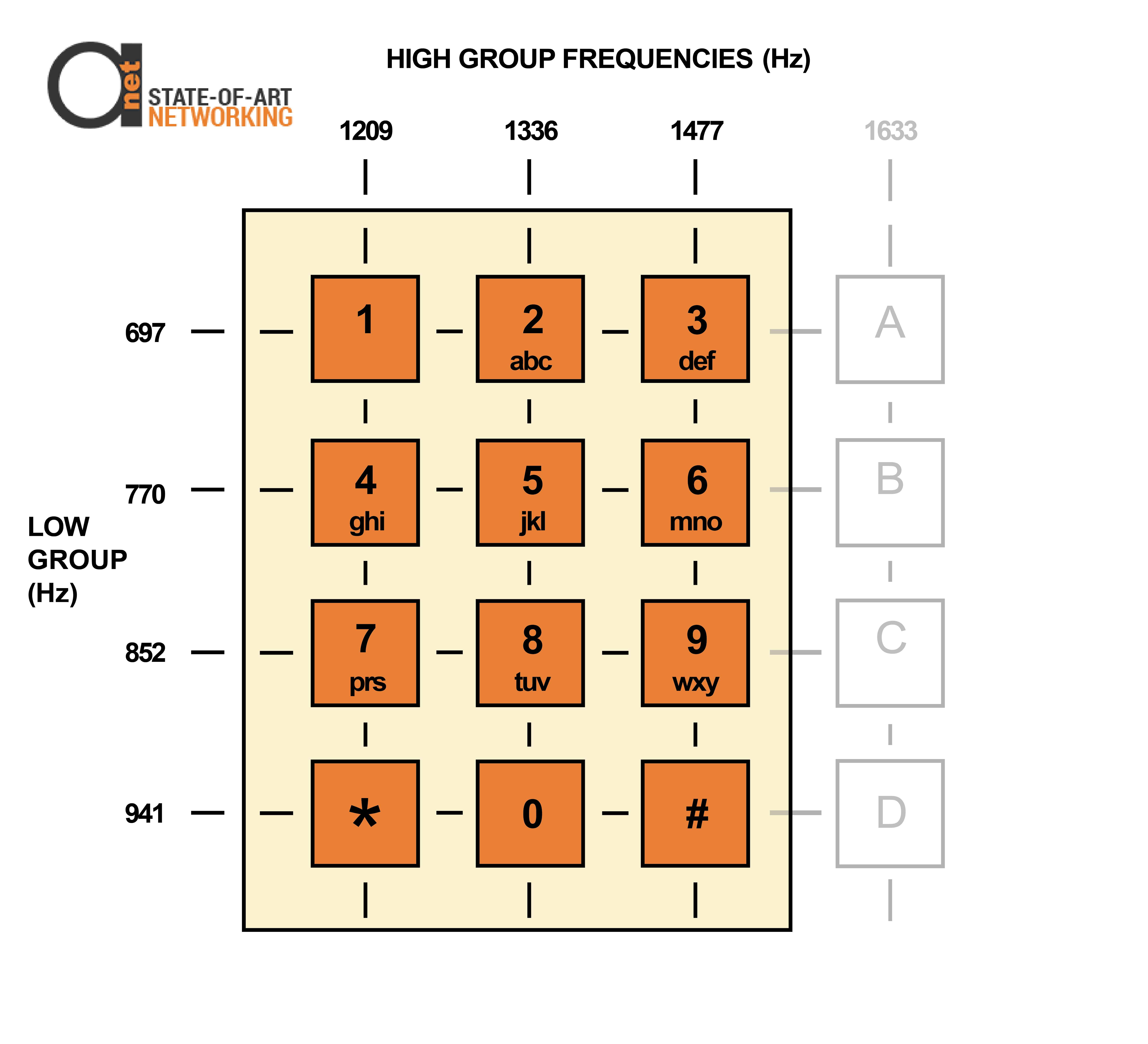
Figure 2: DTMF keypad with “hidden” buttons
Rather than defining one tone per button, which would need 12 tone generators in the telephone and 12 tone detectors on the line card, the tones are arranged in a grid pattern, and two tones are generated to represent each button. Hence the name dual tone signaling.
Using two tones per button requires only 7 tones (3 + 4) instead of 12 (3 x 4). This is much cheaper to implement. To signal the number 4 for example, pressing the button marked 4 generates a tone at 770 Hz and another at 1209 Hz.
DTMF signaling is much faster than pulse dialing, as the button must be depressed for a minimum of 50 ms and the inter-digit interval is only 50 ms for all buttons. A 0 therefore only needs 100 ms (0.1 sec) to be signaled in this way, compared to 1.7 seconds when dial pulsing is used.
In-Band Signaling
DTMF also has an in-band signaling mechanism. All of the tones used are within the voice band, i.e. between 300 and 3300 Hz. This capability used for voice communication is also used to signal control information by using tones within the same frequency band. This allows DTMF to be re-used for signaling between customer premise equipment once a call has been completed. This is for example used to control a voice mail system from a telephone.
Hidden Buttons
Though a standard telephone keypad only uses 12 buttons, DTMF actually defines 16 buttons. The 4 “hidden” buttons are labeled A — D and share the high group frequency 1633 Hz. These tones are only used for special signaling situations, e.g. Call Waiting with Caller ID.
Caller ID
Another example of in-band signaling is caller ID. A 1200 b/s modem in the line card that operates in the voice band delivers the Caller ID to the telephone. With standard Caller ID services, ASCII codes representing the date, time, calling number and possibly calling name is transmitted. This starts 0.5 seconds after the first ring and ends before the second ring.
As the telephone is on-hook during this time, the called party does not hear the modem signal transmitted in the voice band.
The tones used by the 4 “hidden” buttons are used only for special in-band signaling situations. As the Caller ID is delivered with a modem signal in the voice band, the called party would hear the hissing of the modem signal on the line if no special measures were taken. Voice on the line may also interfere with the accuracy of detection of the modem signal.
To solve this problem, the line card generates a dual-tone CPE alerting signal of 2130 + 2750 Hz. This signal instructs the telephone to mute its speaker. The telephone acknowledges with DTMF D. The modem then signals the call waiting Caller ID and as soon as the modem transmission is complete, the telephone unmutes the speaker.
While this allows transmission of a modem signal to send the second Caller ID, it also interrupts the voice communications briefly, which could be annoying to the user.
It is a good example of the advantages of an out-of-band signaling system. In this case, the control signals are not carried in the voice band, but are sent in parallel on a separate channel or control circuit. This capability makes it unnecessary to interrupt a voice conversation to send signals.


