Plain Ordinary Telephone Service ( POTS )
In the industry, basic telephone service is known as Plain Ordinary Telephone Service ( POTS ), and also sometimes referred to as individual residence line service or dial tone.
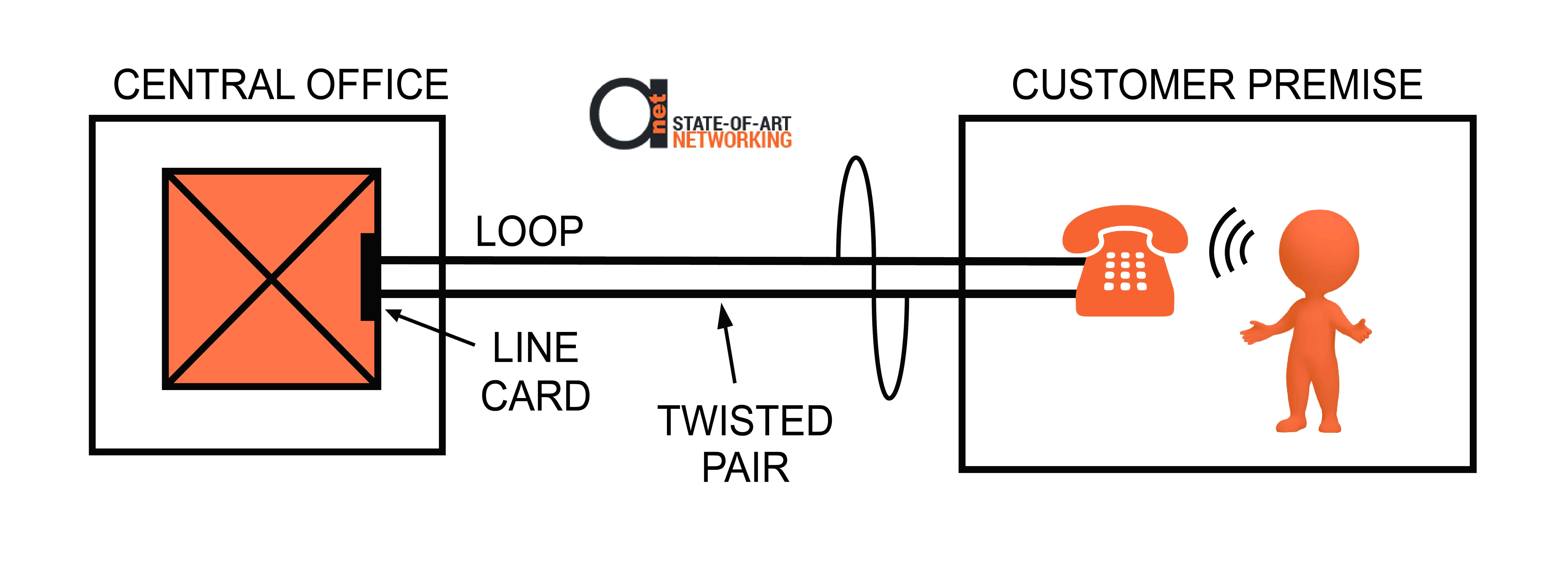
Figure 1: POTS service scheme
As shown in figure 1 above, this service comprises a rotary dial telephone that is connected to a line card in the telephone switch via a copper loop with two wires.
A telephone in POTS systems consists of the following main components:
- Microphone
- Speaker
- Hybrid converter
- Hook switch
- Dial switch
- Ringer
- Protection
Tip and Ring
The two wires of the loop are sometimes still known as the tip and ring. These names come from the first telephone switches that consisted of boards with female jacks. Trunks and loops were connected to these boards.
Operators had to plug one end of a patch cord into the jack for the trunk and the other end into the jack for the loop to connect a trunk to a loop.
The patch cord connectors were designed in such as way that one of the wires was attached to the metal ring below the tip, while the other was attached to the metal tip of a male connector.
The two wires that made up the loop were connected when the connector was plugged into the jack.
Twisted Pair
When two-wire circuits are connected, they act like loop antennas. The quantity of energy picked up by a loop antenna is proportional to its area, and with a telephone, a loop with a diameter of 3 miles (5 km) is used!
The wires are covered in plastic and then twisted together to minimize the amount of noise picked up.
Read more about twisted pairs, in a series of articles here.
Although the wires still act like one big current loop with plastic covering from an electrical viewpoint, from an antenna point of view they act as a series of small loops. The area of the small loops is less than the big loop, thus minimizing the antenna effect of the wires.
Did you know? You can extend POTS telephones a way much father than 3 miles (5 km) – to 20 km, or even 120 km away using AD-net’s Fiber PCM multiplexers.
So, what basically happens here is that you first convert analogue signal to optical light, and then send it to fiber using fiber multiplexers. Scheme will usually then look like this:

Figure 2: Extending POTS lines beyond copper distance limitations using our fiber muxes.
As two wires are twisted together, they are known as twisted pairs. Twisted pairs is used for almost all cabling, including data cabling, inside wiring and telephone wires on poles. LAN cables uses four twisted pairs.
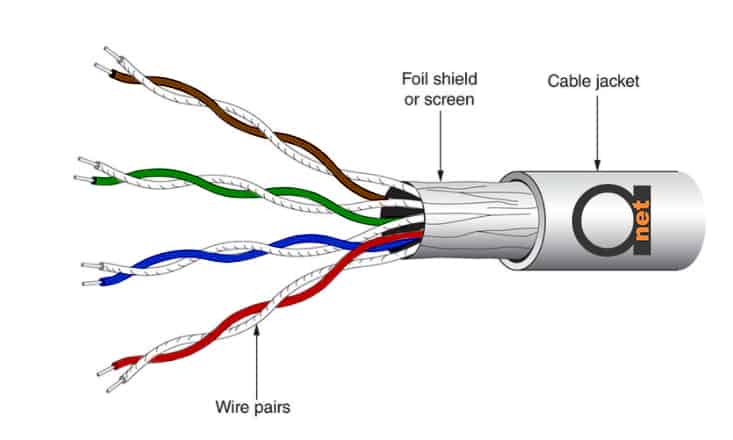
Figure 3: Screened twisted-pair (ScTP)
Line Card
A twisted-pair loop is terminated on a line card on the network side. A line card consists of a small fiberglass board that is populated with components, including connectors and integrated circuits. The line card is plugged into a slot in a drawer that goes in a shelf in a rack. All of this is part of a traditional telephone switch or PABX.
In newer systems, the line card is often part of a gateway that converts between POTS and Voice over IP (VOIP).
The line card has a number of functions, and is sometimes referred to by the acronym BORSCHT: battery, overvoltage protection, ringing, supervision, codec, hybrid and testing.
Microphone and Speaker
A microphone is a transducer that creates a voltage from sound pressure waves. The value of this voltage is a representation of the strength of the sound pressure waves coming from a speaker’s throat.
This voltage is carried from the telephone over the loop to the line card at the near end. It is then digitized by the codec and transported by the telephone network, where it is reproduced by the far-end line card and then sent to the far-end telephone by the far-end loop.
A speaker works to a microphone as it uses voltage received to create sound pressure waves that are sent to the user’s ear.
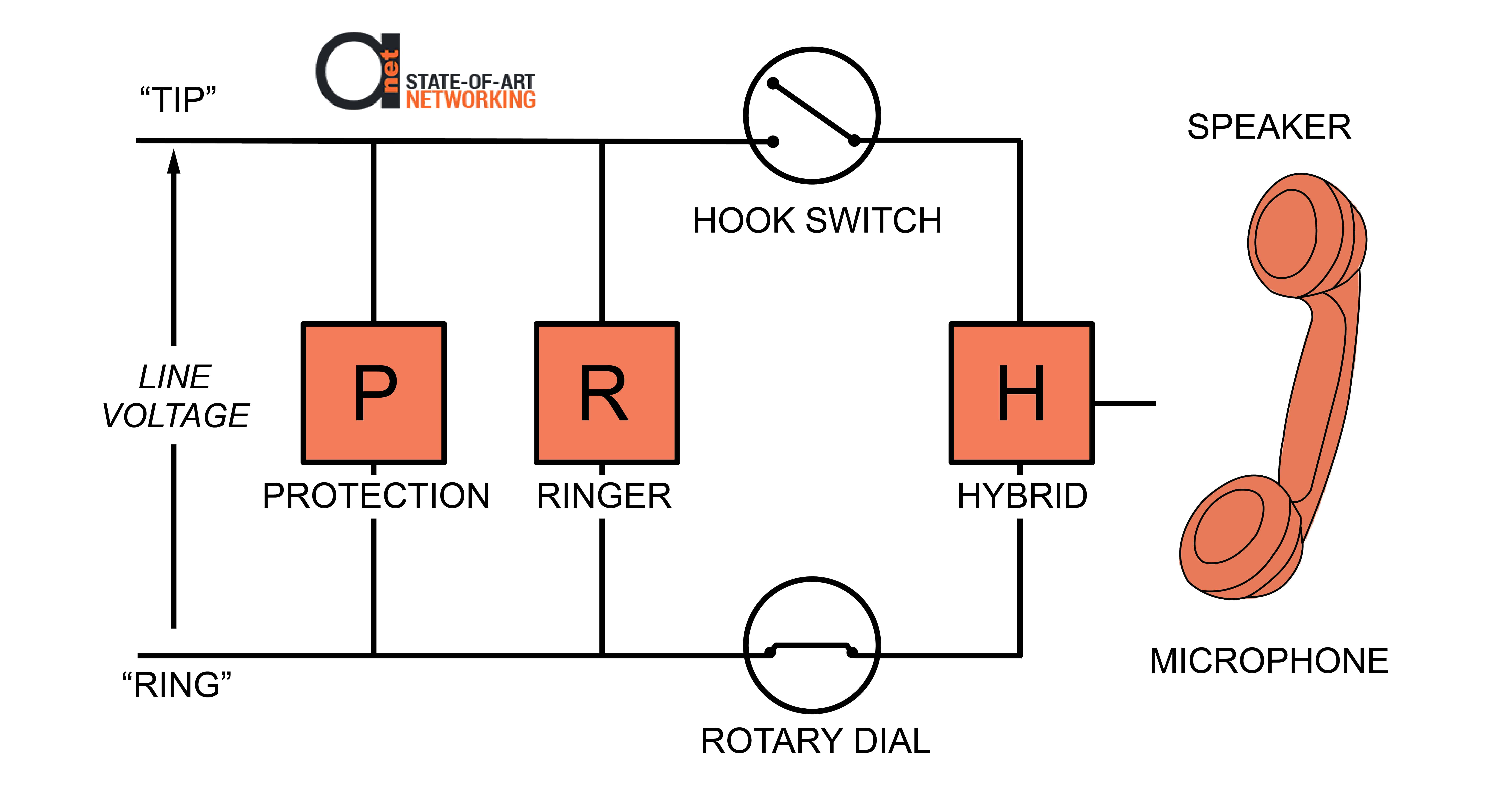
Figure 4: POTS service provision diagram illustrating rotary dial, hook switch, protection, ringer and tip & ring wires.
Balanced Signaling
Voltage is always measured as the difference of voltages between two objects. One object is often the earth, while the other is a wire, so the voltage measured is with respect to ground. With a telephone loop, this is not the case as the voltage is measured between the two wires of the loop, and not between the wires and earth.
In this case, balanced signaling is used. This means that if the voltage on one wire with respect to earth is positive, the voltage on the other wire with respect to earth will be the same value, but negative.
Since noise added will be the same on the two wires, the signal is doubled and the noise is canceled when the voltage between the two wires is measured at the receiver.
Two-Way Simultaneous
The loop’s two wires are used to transmit information in both directions simultaneously. Both the line card and the telephone create voltage analogs of sound across the two wires of the loop. The voltages from the devices at each end are therefore added.
Hybrid Transformer
A device inside the telephone called the hybrid separates the voltage for each direction. The hybrid has two circuits on one side and the two-wire loop on the other side. There is one circuit for the speaker and another for the microphone. A similar arrangement can be found on the line card, connecting the loop to the receive and transmit pins of the codec.
Battery
Apart from the voltage analog of sound, which might be seen as an AC (or varying) signal, the line card also places a DC (or steady) voltage across the two loop wires.
In industry, this voltage is called the battery and it is used to power the telephone. It is nominally -48 volts, measured from ring to tip.
Lightning Protection
The diagram above also shows a protection circuit across the loop. This is to protect the telephone user from being electrocuted by either a high-voltage electrical transmission wire touching the loop, or lightning striking the loop.
Three levels of protection are in fact built into the system:
- A fuse on the POTS line card will blow if too much current passes through it;
- Circuitry on the demarcation point where the telephone company’s wires connect to the customer’s wires will connect to ground if the voltage is too high;
- If the voltage across the loop is too high, a circuit inside the telephone will short-circuit the loop;
Supervision
The ringer and hook switch in the telephone are used for supervision.
Supervision means you must indicate to the other end of your loop that you want to start using the system, irrespective of whom you wish to speak to, or what you are going to say to them.
The hook switch in the telephone is normally open, disconnecting the two wires that make up the loop, and no current or electricity flows in the loop.
The user must pick up the handset (goes off-hook) to initiate communications.
This closes the hook switch and connects the two wires, which allows the line voltage to push current around the loop.
This type of supervision is called loop start signaling as the two wires are connected to form a loop and allows current to flow.
The current is detected by the line card on the telephone switch and it acknowledges with a dial tone.
Variations on this theme are used in other applications such as POTS PBX switches. These include:
- Wink start signaling where line voltage are reversed for a short interval, then returned to normal
- Reverse battery signaling where negative and positive line voltages are reversed
- Ground start signaling where one of the wires is connected ground so the current flows along one wire and then back through the ground
For supervision in the opposite direction, the switch indicates it wants to initiate communications by using the line card to put a ringing signal on the loop.
This is a different voltage that varies 20 times per second. It is applied to the line in a repeating cycle of two seconds on and then four seconds off.
When a POTS phone rings, it is on-hook with the hook-switch open. The ringing signal current flows through the ringer as indicated in figure below.
Original ringers consisted of two brass bells with a clapper between them that would oscillate 20 times per second for two seconds then rest for four seconds. The user accepts a call by going off-hook.
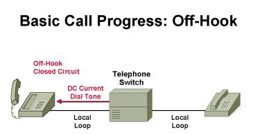
Figure 5: Off-hook on POTS scheme
The line voltages are nominally as follows:
- Off-Hook: -7 to -12 Volts DC.
- Ringing: -48 Volts DC, plus 100 Volts RMS @ 20 Hz
- On Hook: -48 Volts DC
Call Progress Tones
A dial tone is one type of call progress tone. Others include busy, fast busy, congestion, ring-back, howler and sounder tones. The call progress tones are generated by the switch to inform the user of different conditions. Busy signals are generated by the far-end switch, while some tones, such as dial and fast busy tones are generated by the near-end switch.


