Optical fibers are mechanically very different from steel and copper cables, and the techniques for installing them are therefore significantly different. Fibers are not only are extremely brittle, but also elastic to an extent. Fibers must be also be protected from tensile forces (axial), compressive forces and bending.
The long term transmission characteristics of optical fiber depends on the installation procedures used. Fiber laying is a specialized discipline that has to be performed by trained and experience personnel.
Ducting & Trenching
The traditional method of laying optical fibers still used in most developing countries is Ducting and Trenching. This involves creating a trench through manual or mechanized soil excavation. This approach is preferred in countries where manual labor is cheap.
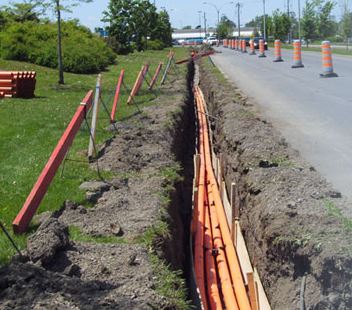
Figure 1: Cable ducts in open trench
Trench specifications are normally defined by local authorities and could be specified for each operator in countries with multiple operators.
The trenching process needs careful control to make sure the trench floor does not have any kinks and is uniform, and trenches do not have major bends.
Ducts are placed in the trenches and fiber is then blown through the ducts with specialized fiber blowers, using water or air. In Air Assisted Fiber Blowing, the blowers use compressed air to push fiber through ducts.
It is standard practice to lay conduits, then draw inner ducts through the conduits and finally blow the fibers through the ducts. A common conduit size is 4 inches (100mm), but 6 inch (150mm) conduits are also available. The size of the inner duct is normally 1.25 inches.
It should be noted that fiber cables should never use more than 70% of the available duct space. When 1 inch fiber cables are used, they occupy 64% of a 1.25 inch duct. Ducts are manufactured from High Density Polyethylene (HDPE). HDPE is hard, can withstand temperatures up to 120°C and have excellent resistance to alcohols, concentrated acids and bases.
Mini Trenching
Mechanized equipment is used to create mini trenches in many different surfaces. This technique can be used on routes that contain asphalt surfaces such as sidewalks and roads. The technique is however not suitable for soil with cobbles or gravel, or sandy soil. This technique has an advantage over conventional cable laying methods in that it is much faster to execute. The cross-section and depth of the trench will depend on the number of ducts to be laid. While the cross-section varies between 7 and 15 cm, the depth is typically between 30 and 40 cm.
Three methods of mini trenching commonly used are:
- Standard
- Semi Automated
- Fully Automated
Trenching, ducting, backfill operations and cleaning are all performed simultaneously when the fully automated method is used. When the standard and semi-automated methods are however employed, the operations are not done at the same time.
Micro Trenching
Micro trenching does not create a deep trench in asphalt as does conventional trenching, but creates a shallow trench, typically 2 cm wide and 30 cm deep. Special micro tubes are then placed in the grooves and it is filled, typically with a cold asphalt. The fibers are then blown into the tubes.
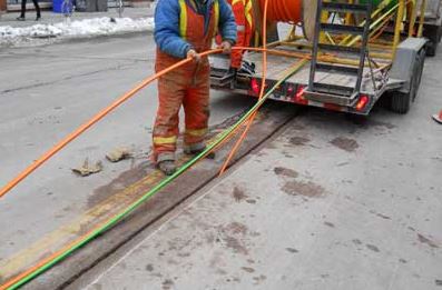
Figure 1: Microtrenching in asphalt
Aerial Cables
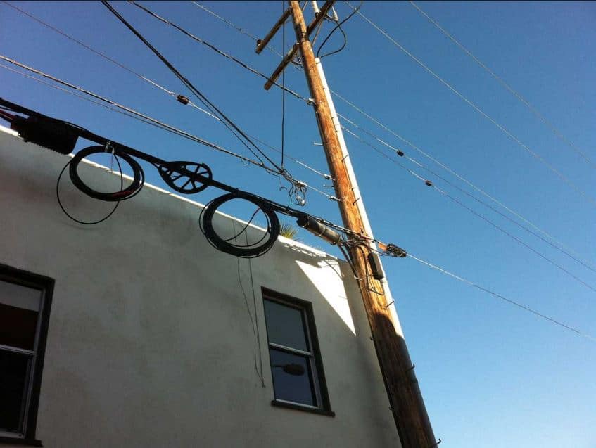
Figure 3: Aerial fiber cables installation example
Aerial fiber optic cables are installed using a technique similar than that used for copper telecommunication cables. It is however important to realize that the transmission characteristics of fiber is affected by compressive stress, tensile stress and bends, making it essential to ensure that cable sag is within acceptable limits.
Messenger or support wires made from Galvanized Iron (GI) provide support for the fibers strung between GI, or other suitable poles. The lashing of fiber optic cable is done using two methods – the Stationary method and the Moving Reel method.

Figure 4: Messenger or Support Wires
With the Stationary method, the cable is pulled into place using cable blocks, while the Moving Reel method employs reel carrying vehicles on the entire route of the fiber. Cables best suited for aerial installations are All Dielectric Self-Supporting (ADSS) cables.
As the name implies, ADSS cables do not need supporting or messenger wires.
Cables Buried Directly
This fiber laying technique consists of using specialized equipment to create tiny incisions in any surface including concrete and asphalt.
The fiber cable with a protective covering is then laid and the groove is filled with epoxy. The protective covering protects the fiber against the tensile and compressive forces that fibers are commonly susceptible to. This technique is conceptually the same as micro trenching, but does not require ducting. The technique is commonly used in urban areas where right-of-way permissions for standard trenching and ducting can’t be obtained.
On farms, fiber cable should always be buried below the maximum depth reached by agricultural equipment.
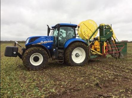
Figure 5: Fiber Laying system on tractor
On the other hand, the burial depth on highway and road crossings should be enough to avoid cables being damaged due to maintenance activities and road grading. Generally, the depth for these cables would be 12 inches.
Horizontal Directional Drilling
Horizontal Directional Drilling (HDD) is also referred to as Directional boring, and is a trenchless technique used for installing conduits, underground pipes and cables.
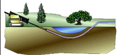
Figure 6: Principle of Horizontal Directional Drilling (HDD)
For this type of installation, a drilling rig that is launched from the surface is used to create a shallow arc along a predefined path. The impact on surrounding areas using this method is minimal and it is therefore preferred when excavating or trenching is not practical. It can be used for numerous soil conditions and jobs including landscape, road and river crossings. Some cities will only issue Right-of-Way (ROW) permissions for HDD based cable laying.
The process is multi staged and the first step involves creating an entrance pit with a receiving hole. A pilot hole is then drilled through the designed path, after which the hole is enlarged (reamed) with a larger cutting tool known as the back reamer. The diameter of the reamer is determined by the size of the pipe to be pulled back through the hole. In the next stage, a casing pipe is placed in the enlarged hole by using the drill stem. A fully automatic gyro based drilling mechanism is used by advanced HDD machines.
Thus, we can make a summarizing in following picture below:

Figure 7: Summary of Fiber Laying Techniques


