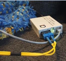
The term optical transmitters refer to the source of light in an optical system.
It is fairly obvious that the light sources are an integral and a crucial component of a fiber optic network. The span length, the number as well as the placement of regenerators and amplifiers (like EDFA’s) are all dependent directly or otherwise on the transmitter types.
That’s a phase 1 of evolution of fiber networks, you can read more about it here.
In all commercial applications as well as equipments the conversion of signals from electrical to optical and Vice-versa is done by an integrated electro-optical unit (E/O)that functions as a transmitter and receiver.
The issues of thermal dissipation, efficacy of heat sinks, size, and method of coupling the optical power onto a fiber are all taken care of the manufacturer and in most cases the users would not have much say in the same.
The modern day architecture consists of racks or skeletons which are equipped with cards also referred to as plug-in-units or plug-in-cards (PIU or PIC). AN-CH05 media converter chassis is an example of such PIC and PIU system.
The electro/ optical (E/O) unit is integrated with other functional components and would be in the form of a plugin-card the user can only decide among the various types of cards offered by the manufacturers, based on certain parameters discussed later in this chapter.
In this post we will focus only on the transmitter which serves two major functions:
1. Provide a source of light for transmission over the fiber
2.Modulation of the source in accordance with the transmitted data.
The former (point 1) involves emission and the subsequent coupling of light onto a waveguide which is nothing but the fiber.
The second function involves the variation of the intensity of light being coupled onto the fiber.
The olden day transmitters were fabricated using discrete electrical as well as electrooptical components. These were subsequently replaced by integrated circuits (IC) of varying designs starting from small scale integration (881) to the current multilayer very large scale integrated (VLSI) chipsets. The commonly employed optical sources include Light Emitting Diodes (LED), Laser Diodes (LD) as well as Vertical Cavity Surface Emitting Lasers (VCSEL).
Like we discussed in this article, applications that commonly use VCSELs include spectroscopy, fiber optic communication, laser printers, broadband transmission (Analog) and optical mouse. Some models of Multimode Fiber Media Converters use MM VCSCEL lasers.
Read more about differences between Lasers and LED’s here.
Following are some of the important design considerations for a transmitter:
- The physical dimensions must be compatible with the size of the FCC being used.
- This implies that the emitted light must be coupled into a cone with a cross sectional diameter 8-100 microns.
- The optical source must be able to generate enough optical power so that the desired bit error rate (BER) can be met.
- In order to ensure the optimal usage of the high bandwidth offered by the FCC, the optical source must be capable of being modulated by a high frequency electrical signal.
- The coupling efficiency (the amount of power that is actually transmitted along the fiber) should be high.
- The source should have a high coupling efficiency.
- The linearity of the optical source should facilitate the suppression of harmonics and intermodulation distortion.
- The source must be made available in a compact low footprint, low weight package with and high reliability.


