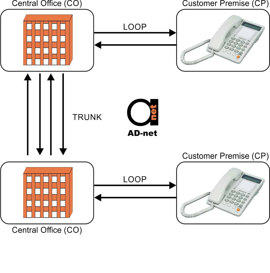
We’ll start this series of articles with a basic model of PSTN – PSTN stands for (Public Switched Telephone Network) and build on it in subsequent posts. In figure below, at the top, a telephone and a telephone switch is shown. The telephone is located in the Customer’s Premises (CP, CPE), while the telephone switch is located in the Central Office (CO).
In this scenario, the telephone could be referred to as Customer Premise Equipment (CPE).

Figure 1: Most basic representation of PSTN – (Public Switched Telephone Network).
Loops
Two copper wires are used to connect the telephone to the telephone switch. These wires are known as a local loop, a subscriber loop, or simply a loop. The loop is a dedicated access circuit from the customer’s premises to the network.
At the other end, the same arrangement will be found with another telephone in a different customer premise and its associated telephone switch in a different central office.
Although copper is a good electricity conductor, it’s not perfect as it has some resistance. This resistance will cause the signals in the loop to attenuate with distance, or diminish in intensity.
The maximum resistance permitted in a loop is 1300 ohms, which is reached in 18,000 feet (5 km / 3 miles) on standard 26-gauge cable, but it could be as long as 22 km / 14 miles on thicker, 19-gauge cable.
Hint: More about Copper cable gauges, check this article.
This maximum loop length of 5 km / 3 miles defines the traditional serving area around a Central Office, which translates to about 75 square km / 27 square miles.
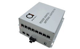
Now, typical loop extender in our products are this series POTS fiber voice multiplexers. They take copper line POTS port, and extend it over fiber for 10, 20 or even 100 km away:

Figure 2: ADnet’s 8 port over fiber copper line extender series.
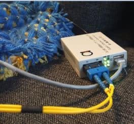
In this case, typical scheme you will see on our product pages are kind of this:

Figure 3: Extending copper loop via fiber using fiber optical multiplexers.
Now, can you spot some first differences in terminology here? Now, Loop here technical is not only a simple copper cable from telephone switch to extension phones (CPE’s), but also includes more active extension equipment like fiber muxes, and there’s a fiber in middle between these multiplexers.
For a quick article describing main differences between fiber and copper as media, go here.
Trunks and Circuit Switching
Trunks are used to connect telephone switches. Trunks are shared connections between COs, as opposed to subscriber loops which are dedicated access circuits.
To establish a connection between two customers’ premises, the calling party has to signal the network address (the telephone number) of the party being called over the network via their loop, or more specifically, to their switch in the CO.
The switch then makes a routing decision for the phone call and implements it by using an unused trunk circuit going in the right direction, and connecting the loop to it.
The network address of the called party is signaled to their switch, which then connects the trunk to the right loop. When the called party picks up their phone, an end-to-end connection is established and maintained for the call’s duration.
When either party hangs up, the trunk is released for new connections.
This method for trunk sharing is known as circuit-switching, and was called dial-up when telephones still had rotary dials.


