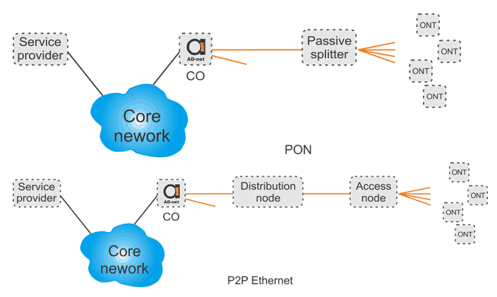
Figure 1. illustrates generic design of P2P Ethernet network. The access network is a melting pot of different technologies, so there is no single or correct way of calling different parts of the network. In simple pon, the Central office/Central node/head end is connected to service providers through the Core network. On the other side, Central Office is connected to a distribution node/access node/regional node which is connected to number of access nodes. Access nodes are then connected to number of customers equipment. Different machines (e.g. computer, TV, IP-telephone) are connected to customers equipment allocated on customers premises.

Usually, Central Office is an IP router which directs traffic towards individual customer premises equipment. Transitional equipment is layer 2/ layer 3/ mix of both. The distribution node is most frequently an L2 switch, while access node is either an L3 device or a L2 switch with limited L3 functionality. IP based services are always carried encapsulated in Ethernet frames. Decision on using either L2 or L3 equipment is based on several factors:
- security
- cost
- future proof
- availability of interfaces
- amount of supervision required
If a network is large it may require constant supervision and high degree of automation. On the other hand, municipality might be limited by budget so network will not be much future proof. The security and integrity of L2 solution cannot be guaranteed with a reasonably scalable design. The problem is solved by integrating L3 functionality in the switch design by main manufacturers.


