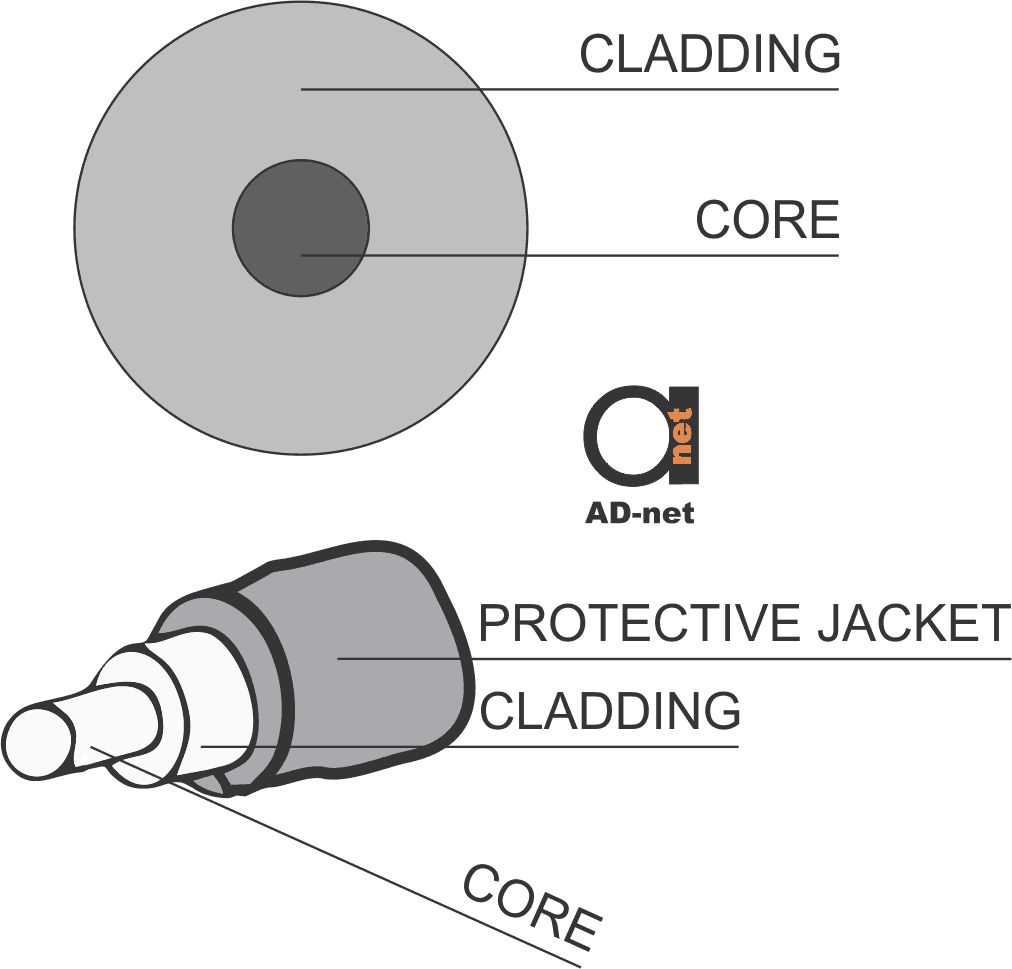
An optical fiber is comprised of a pair of unique layers (differing refractive indices —RI) made of pure plastic or glass, which are arranged to form the cladding and core.
The outer layer is formed by the cladding while the inner layer forms the core. Several layers of coating protect the cladding so it can endure various pressures while deployment occurs.
This protective coating is usually made of a gentle interior layer developed to cushion the fiber, as well as a solid exterior layer developed to withstand pressure while termination or installation is taking place.
The important design parameters of an FOC (fiber optic cable) is introduced in this blog post. They are comprised of light propagation modes, attenuation aspects, safety standards, optical fiber types, and more. In figure 1, you can see a picture of the optical fiber’s cross-section.

Figure 1: An Optical Fiber’s Sectional Perspective
Losses
There are individual loss types encountered during light propagation through a medium. This section outlines the main instigators of light attenuation flowing through an optical fiber. Figure 2 displays the attenuation aspects of a regular single-mode optical fiber.

Figure 2: Attenuation db/km per wavelength in fiber optical cables
Now, here’s a graph you can use to estimate loss you will get using various wavelengths of your equipment. Like for example, if you choose regular Gigabit Ethernet Media converter with 1310 nm wavelength, it will work on shorter distances like the one with DFB type 1550 nm laser. Those can work on 100 km and more.
Besides that, remember, that some equipment uses 2 wavelengths same time, separating Transmission and Receiving, like WDM Gigabit Media Converters use 2 wavelenghts 1310/1550 nm and GPON systems – 1490/1310 nm and 1550 nm for CATV overlay.
Absorption
Light is comprised of a photon stream. Absorption refers to signal energy loss because of the absorption of the propagating photons through a media and its subsequent transformation to heat.
Scattering
Scattering produces light redirection via the core onto the cladding.
Dispersion
As one of the main contributors to light transmission loss over an optical fiber, dispersion refers to the flexibility of light waves as it flows along the fiber.
As you can see in figure 3, dispersion influences the propagating signal through the fiber, which significantly degrades it over a distance. There are typically a couple of dispersion sources: intermodal dispersion and intramodal dispersion. Intramodal dispersion can transpire in all kinds of fiber and can be further defined as:
- Waveguide dispersion;
- Material dispersion;
Waveguide dispersion is the result of the connection between the propagating light signal and the waveguide’s physical dimensions (core diameter). The frequency-reliant reaction of a media to the propagating light is known as material dispersion.

Figure 3 — Types of Dispersion – Intramodal (Chromatic) vs Intermodal
The pulse spreading resulting from a specific glass composition is known as material dispersion.
Waveguide dispersion happens when light travels in both the inner and core-cladding glasses simultaneously at unique speeds. Both types can be balanced to create a zero-dispersion wavelength anywhere between the 1310 nm to a 1650 nm operating window.


