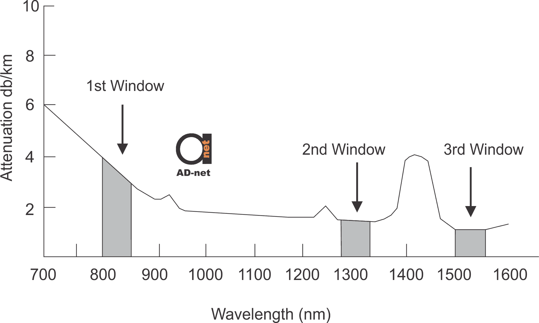
In the early days of fiber optic communication the LED was employed as a light source. The LED’s mostly operated at the 780 nm or the 850 nm wavelength. This region is referred to as the first transmission window.
The LED’s could not be employed for high bandwidth transmissions over a long distance due to their inherent disadvantages (explained later in this post) and was replaced by lasers. Laser’s operated in two wavelength regions namely 1310 nm & 1550 nm that are commonly referred to as the second and the third optical transmission windows.
The effects of dispersion are zero at the 1310 nm window whereas the losses are the least at 1550nm window. The modern fiber optic networks operate around 1310 nm and 1550 nm, also 1490 nm is gaining steam because of GPON systems.
1550 nm wavelength band is also particularly important to the WDM networks that are increasingly being deployed in networks worldwide. These networks use amplifiers to counter the effects of attenuation. The commonly deployed amplifiers are the Erbium-doped Fiber Amplifiers (EDFA) that provides signal amplification across a range of wavelengths around 1550 nm and 1625nm. This window is commonly referred to as the EDFA window. The optical transmission windows are as depicted in the figure 1.

Figure 1 – Optical Transmission Windows
That’s also important concept for ordering any passive optical network devices, such as optical cable itself, or splitters – it’s important to check specifications or ask your supplier, what optical windows are supported? Is it dual window or single window?
Propagation Modes
Light is propagated through the “core” of an optical fiber by the principle of total internal reflection, discussed in the subsequent section. This optical fiber thus acts as a waveguide. Light traveling through a FOC exhibits certain modes or variations in the intensity of the light as it travels over the fiber.
The number of modes that can exist is dependent on the cable dimensions as well as the RI’s of the core and cladding. Fibers which support only a single mode are called single mode fibers (SMF) while those providing multiple propagation paths referred to as multimode fibers (MMF).
The commercial fibers available in the early days of optical communication had a large core diameter facilitating multiple modes of light to simultaneously propagate through the fiber. The larger core diameter of these multimode fibers also facilitated the use of lower-cost optical transmitters.
A Single-mode fiber has a small core diameter that allows only one mode of light to propagate through it. Hence the optical signal can travel over longer distances in the absence of modal dispersion. It is interesting to note that there, as commonly perceived the multimode fiber does not provide a higher transmission bandwidth as compared to a single mode fiber.
SMF are the preferred choice for deployment in telecommunication networks as well environments requiring long distance, high bandwidth applications. It’s the default choice for really hot FTTx PON developments now – only single mode type cable can be used from OLT to ONU’s, and will not work over Multimode type cables. Does not matter, if it’s GPON or EPON, both requires Single Mode Type cables.
Multimode fiber is used principally for systems that need to communicate over short distances (typically less than 2000 meters). This could include communication between equipments within an industry or communication inside optical multiplexing equipments or between communication equipments within an exchange.
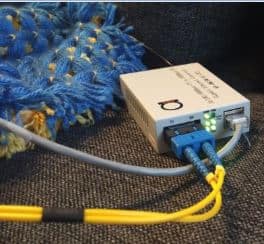
Remember, that everything yellow jacket color for optical pathcords, will be Single Mode type, while orange jacket will signify, that you have got multimode cable in hands.
Like if you see this video:
… you can immediately notice orange color of fiber jacket, means we’re testing here our Multimode Fiber Media Converters.
While here, it’s yellow:
That means, 8 ports of High Resolution AHD Video signal in above video will be sent over single mode type cable on distance at 20 km using our AHD/TVI/CVI over fiber converters series.


