This is a next article in series about OSI layer 1 – in previous articles we looked at Introduction to OSI Layer 1, then OSI layer 1 in a perspective of Ethernet, and also OSI Layer 1 through Legacy Ethernet protocols.
Next, we’re going to take a look at same layer even deeper, one when link concepts that should be understood before you go deeper into your networking concept studies.
Let’s get started with CSU/DSU connections.

Figure 1: DTE/DCE concept in networking
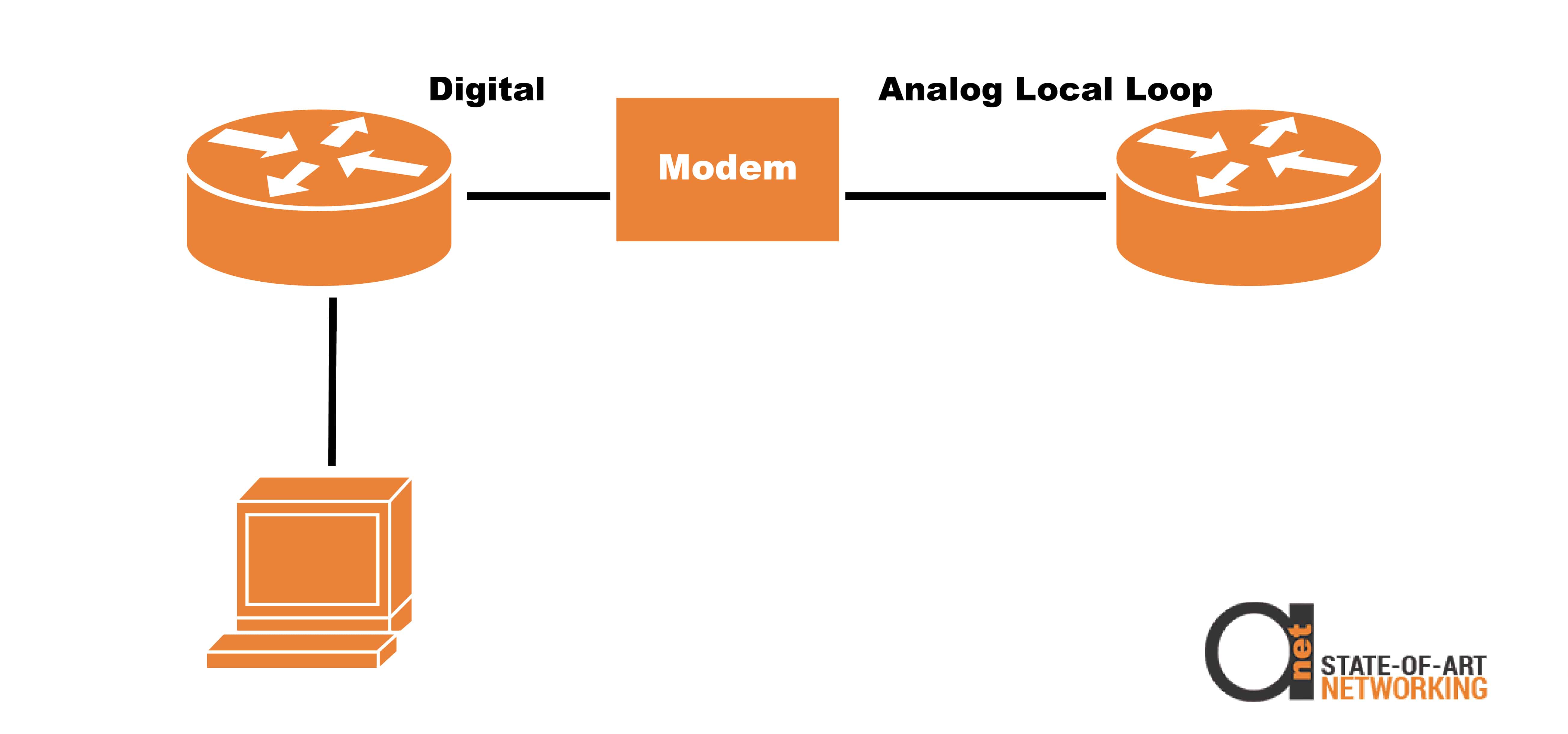
These are going to be connections for digital signaling, for communications from your local customer equipment to a digital connection to the provider.

Figure 2: Digital vs Analog Local Loop
While the customer side would be considered to be the DTE connection and provider side would have the DCE connection. The main thing to know here is that the DCE provides clocking while the DTE receives it.

Figure 3: Clocking is always coming from DCE side
The clocking, this clocking is used to synchronize your circuit speed, which is configurable on the DCE end. A couple of important things to understand for the exam would be that a modem connects to an analog local loop while your CSU/DSU connect to digital local loops.


