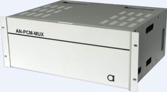
PCM Oriented Multiservice Platform
AN-PCM-MUX is a PCM MUX equipment. It converts analog voices into 64 kbps digital signals, and multiplexes the tributary 64kbps signals into primary rate E1 signal, to be transmitted over E1 transmission channels. It can be used to extend the reach of voice and data services from the central office to remote user sites.
- Maximum capacity up to 60 PCM channels per enclosure.
- Built-in cross-connect functionality.
- Supports multiple user interface types, including traditional telephone, Co-directional 64kbps data, async RS232 serial data, public telephone, hot line telephone, magneto line interface, 2/4 wire voice, EM signaling, 10Base-T Ethernet, Nx64 kbps V.35 data etc.
- Flexible configuration, different types of interfaces can be freely mixed in a single shelf.
- Compact size, easy maintenance.
- 1+1 Power card redundancy for high reliability.
E1 interface
Bit Rate: 2048kbps±50ppm
Line Code: HDB3, comply to ITU-T recommendation G.703
Impedance: 75W (unbalanced) or 120W (balanced)
Frame Structure: Comply to ITU-T recommendation G.704, G.706
Companding: A law, comply to ITU-T recommendation G.711
Signal level: ±2.37V±10% @75W, ±3V±10% @120W
FXO (daughter card CH/L, connects to exchange)
Off-hook impedance: < 500W
On-hook impedance: > 10KW
FXS (daughter card CH/R, connects to telephone)
Loop impedance: £ 2000W (including telephone)
Idle loop voltage: £ 50V
Loop current: 25mA
Off-hook threshold: 8mA
Polarity reverse delay: < 50msec
Dial: Pulse width distortion < 5msec
DTMF total frequency distortion comply totelephone interface specifications
Off-hook delay: < 100msec
Standard 2-wire (daughter card CH2W)
Impedance: 600 W
Frequency range: 300-3400 Hz
Companding law: ITU-T G.711 A-law
2-wire interface signal level:
transmit: 0dBr ± 0.5dBr
receive: -3.5dBr ± 0.5dBr
Return Loss: 300-600Hz >12dB
600-3400Hz >15dB
Frequency response: 300-3400Hz, comply to ITU-T G.713
Background noise: £ -65dBm0p
Gain: -45dBm0 ~ +3dBm0 (within ±0.5)
Total S/N: Comply to ITU-T G.713 mask
Magneto Interface
Standard Magneto (daughter card CHRD)
Voice specification identical to standard 2-wire voice interface.
Ringing detection: minimum 20Vrms, detection time: <0.5s.
Signalling: digital (PCM time slot 16 code a)
Synchronous Data Interface
G.703 64kbps interface (daughter card CHD)
Line code: comply to ITU-T G.703
Data rate: 64kb/s codirectional
Low speed V.35 interface (daughter card CHD_V35)
Interface signal level: ITU-T V.35 / V.11
Data rate: 64kb/s codirectional
N*64K V.35 interface (channel card DATA2)
Interface signal level: ITU-T V.35 / V.11
Data rate: N*64kbps(N=1 ~ 30, codirectional)
Asynchronous data interface ( daughter card CHAD)
Interface signal level: RS-232/V.24 or RS-422/V.11
Data rate: £ 14.4kb/s
10 Base-T Ethernet Interface (channel card 10BASE-T)
comply to IEEE 802.3
Hot Line Interface (daughter card CHP)
Loop impedance: £ 2000W (including telephone)
Idle loop voltage: £ 50V
Loop current: 25mA
Off-hook threshold: 8mA
Control Station Interface
4-wire RS-485, TABS protocol, 9-pin D type connector, 2.4kbps, 8 data bits, 1 stop bit, odd parity.
Power Supply
Supply voltage: -48Vdc
Voltage range: -40 ~ -65Vdc
Power comsumption: SU unit <0.6A/60ch (@-48V, all channel idle)
CO unit <0.4A/60ch (@-48V)
Dimensions
W´H´D: 432mm ´ 178mm ´ 345mm
Description
AN-PCM-MUX is a PCM MUX equipment. It converts analog voices into 64 kbps digital signals, and multiplexes the tributary 64kbps signals into primary rate E1 signal, to be transmitted over E1 transmission channels. It can be used to extend the reach of voice and data services from the central office to remote user sites.
To meet the needs of different customer requirements, AN-PCM-MUX provides a wide range of voice and data interface choices.
The equipment can be remotely monitored through the management software.
AN-PCM-MUX is usually configured as central office side (CO) or subscriber side (SU) units. The CO unit connects to the telephone exchange line card, while the SU unit connects to user telephones. The CO unit converts the voice signal from the central office exchange telephone interface into digital PCM signal, and convert the ring voltage and other DC signaling into channel associated PCM signaling, multiplexed into E1 signal, and transmitted to the remote, and the SU unit demultiplexes the E1 signal into individual tributary digital signals, convert back into analog voices, and sends out to the subscriber line leading to the user telephone set. The signaling is also converted back to ring voltage on the telephone line.
The AN-PCM-MUX can be monitored through RS232 and RS484 supervision ports on the PCM Mux Card. To monitor the cards installed in both sides of the connected pair, a PC based control station can be connected to either the CO side or the SU side, although most applications place the control station at the CO side.
The AN-PCM-MUX has the following building blocks & daughter cards:
- 19” 4U Enclosure Shelf (include backplane)
- Power card — PWR
- Ring Power Card — RPWR
- PCM Mux card — MDX1-|
- Channel mother card — CHU
- Nx64kbps V.35 data card — DATA2
- 10 Base-T Ethernet card — 10BASE-T
- E&M signalling card — EM
- FXO daughter card — CH/L
- FXS daughter card — CH/R
- Standard 2-wire daughter card — CH2W
- Standard 4-wire daughter card — CH4W
- 4-wire+attenuator daughter card — CH4W-A
- Standard Magneto daughter card — CHRD|
- Carrier signaling magneto daughter card — CHRD-2K|
- 2100Hz signaling generator daughter card — (SG_2K)
- 64kbps G.703 data daughter card — CHD
- 64kbps V.35 data daughter card — CHD-V35
- Asynchronous data daughter card — CHAD
- Hot line daughter card — CHP

