First part of this series click here>>
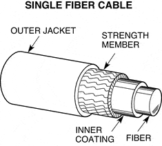
Buffer is the protective layer of the fiber cable that cushions fiber from itself from the outside stress. There are two types of buffers – tight and loose tube.
Tight buffer is usually made of PVC or Nylon and is applied directly on top of the optical fiber or fibers. Tight buffer makes termination and installation process easier. However it is only used indoors, due to inability to work in temperature changing environment. Temperature changes expand buffer which transmits expansion and contraction forces to the fiber. Constant force is damaging the fiber strand creating transmission errors or disrupting transmission completely. Nevertheless, cable manufacturers offer special outdoor solutions with tight buffer that are able to work in rough environments.
Loose-tube buffer is a plastic pipe that accomodates one or several fibers inside. Empty space in the tube is filled with protective material that would ensure cables strength. Protective materials include different water blocking gels. Additionally, cable would be waterproofed with water blocking powders and tapes.
Loose-tube buffer absorbs almost all the external forces that might affect it depending on the environment. It makes it number one choise for the outdoor installations.

Optical fibers are extremely fragile during cable installation. Strength members are intended to provide additional support to the cable, preventing breakage of optical fibers. In the tight-buffered cables strength member is placed around buffered optical strand. Usually it is made of strands of aramid yarn, which is highly durable material. These strands absorb the pulling force during installation, so the cable’s core would remain intact. However, installation of such cable would require additional tool – aramid scissors. Ordinary cutting tool is not able to cut this strngth member’s strands.
For the loose-tube cables strength members usually use steel or fiberglass. There are two possibilities of how this cable could accomodate strength members. First option positions the strength wire in the middle of the cable, surrounded by multiple fibers. Second option offers additional external force protection, with strength member surrounding optical fibers from outside. both ways offer pulling force absorbtion as well as compression-induced microbending happenning at extremely low temperatures (below -40C or -40F)
For extra physical protection, cable might have additional layer of metallic shields. It only offers physical protection, since fiber is not exposed to EMI. However, it should be grounded on both ends.
Outer jacket is made of plastic material, comes in different colors and should meet fire resistance requirements.


